
Project Development
MR. Flippers

Week 1
This week, I worked on the basic circuit, identified key components, and made a rough sketch of the final design.
Reference Circuit
We made a basic circuit for practice in Canva using the key components we listed:
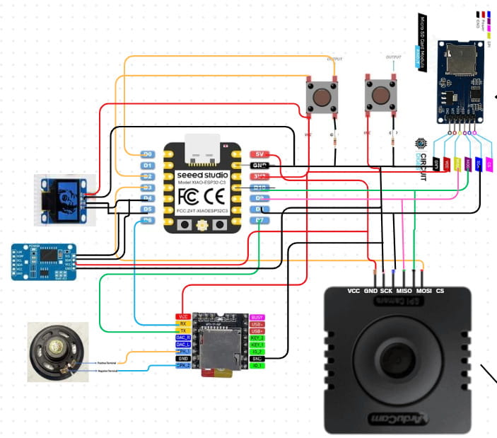
These are some of the things I learned that time:
- Choose the components: First, identify the specific components you need for your circuit.
- Check compatibility: Make sure each component can work with your board. A good way to do this is by searching the component name along with the board (e.g., “DS3231 RTC Arduino”) to see if it has been done before. This helps avoid last-minute issues with incompatible parts. Save the connection reference that is the clearest to you.
- Find the pinouts: Look up the pinout for each component (for example, “Arduino pinout” and “DS3231 RTC pinout”). The pinout tells us the specific connection for each pin. Each pin has a specific function, so it’s important to check the pinout of both components when connecting them. Some pins are meant to receive input from a specific output pin, while others send output. Each pin handles a particular type of signal, like power, ground, or data, and connecting the wrong pins can cause the circuit to fail or even damage components. There are many references, like images, showing the pinouts of components. Save the one that is the clearest and most detailed for your use.
- Connect the pins: Using the connection reference and the pinout information, connect the required pins carefully, making sure each pin goes to the correct spot.
- One more thing to keep in mind: all the GND (ground) pins in a circuit should be connected together. This creates a common reference point and provides a path for electricity to safely flow back to the source, completing the circuit.
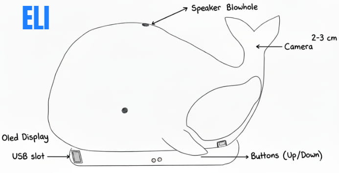
I was also able to make a draft sketch for my final project. Although it isn't very detailed, it represents what I have in mind for now, even though it will likely change a lot as the project develops. I then refined the image using Gemini AI, so credit goes to Gemini AI.
That's all for this week.
Week 2
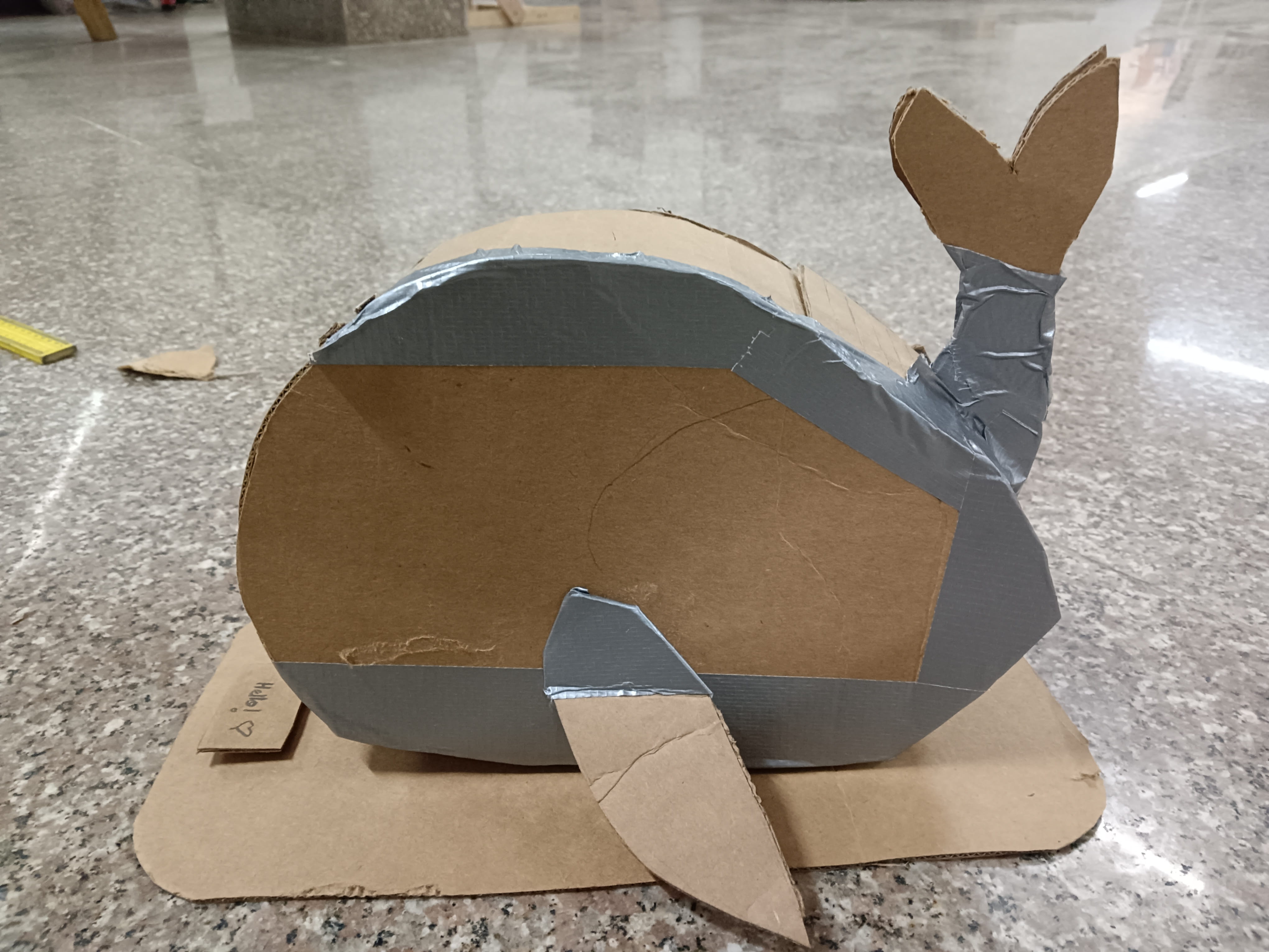
This week, we went to the lab to do cardboard prototyping. We created detailed cardboard versions of our final projects to better understand how all the components would work together, visualize the final design, and identify gaps that needed improvement.
This was my prototype of my final project which is a desk bot that trains your focus. For more details about my project, you can visit the Project Proposal page on my website.
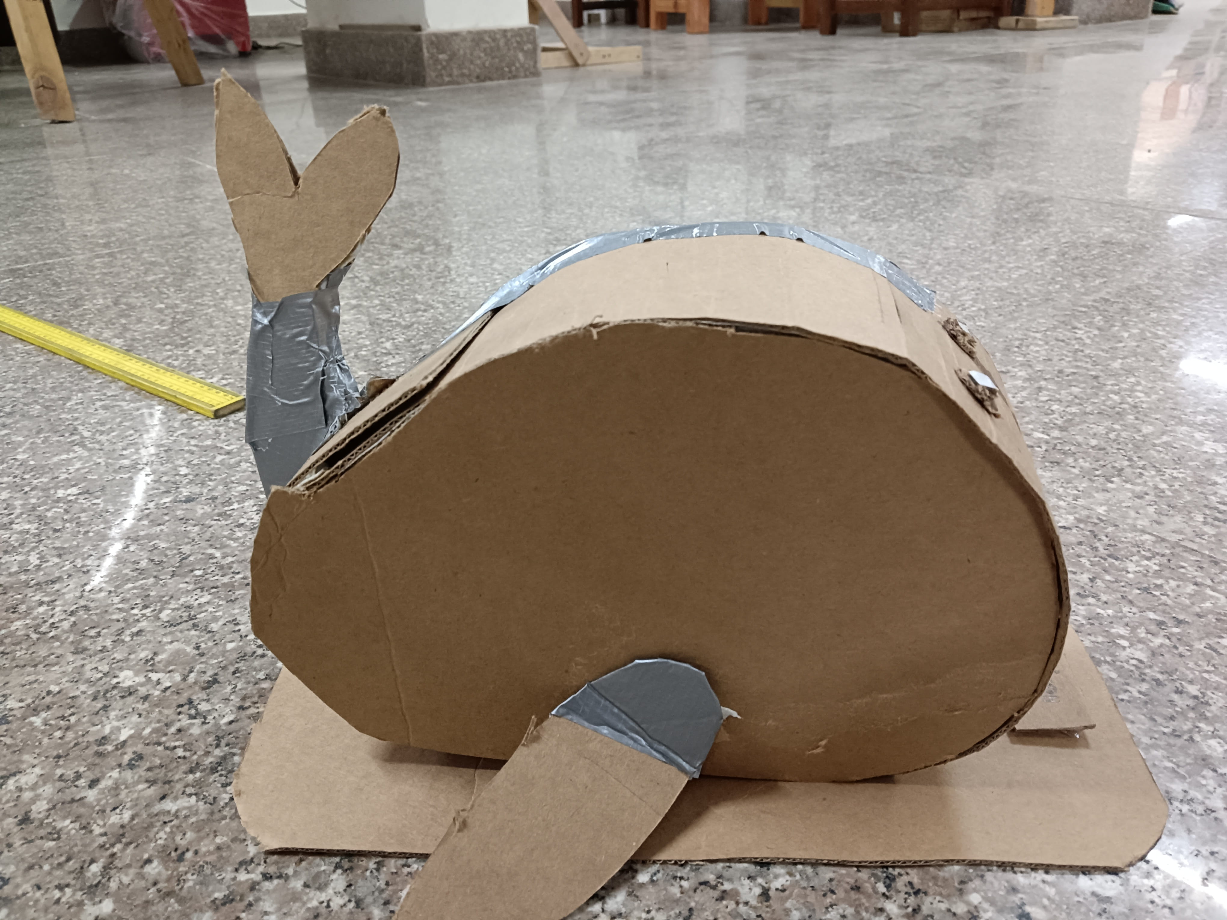
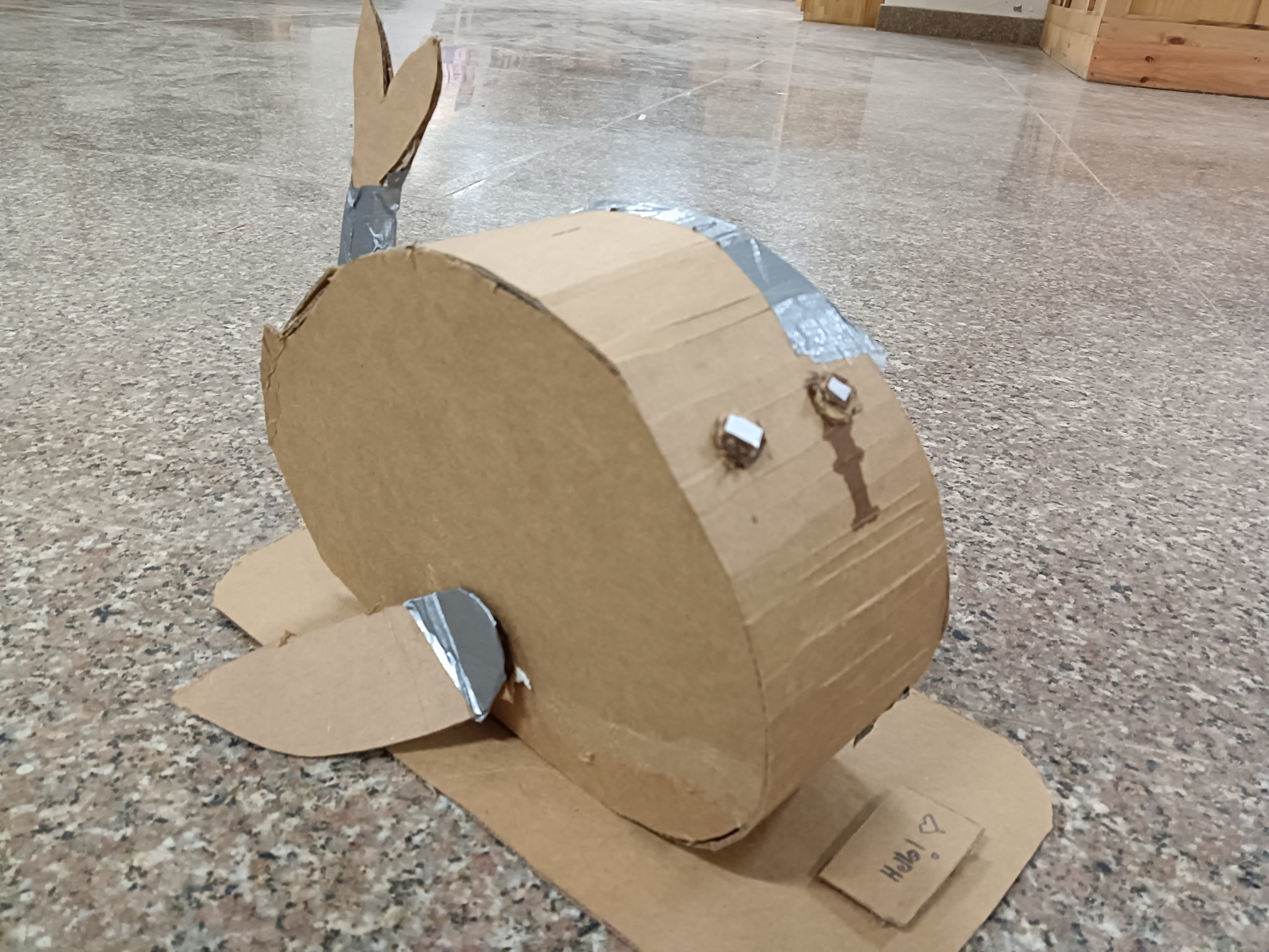
Through this experience, I was able to identify several gaps in my project idea and realized that I needed to work out many details instead of keeping everything abstract in my head.
Gaps identified:
- Camera orientation: Where will the camera/cameras be placed? On the tail or on the front of the body?
- Input method: How should users input data? (Fins, buttons, sensors, etc.)
- Casing: How can I open the bot easily to check internal components?
- Data Logging: How can data be logged efficiently without making the process too complicated?
- Menu Structure: What should the home menu look like and how should navigation work?
- Measurements: What are the exact measurements for internal and external fits?
- Internal Layout: How should connections be arranged for correct component placement?
Reviewing these gaps, I can categorize them into two important challenges for myself:
- 1. User Interaction and Interface (UI): Input method and menu structure.
- 2. Mechanical Design: Camera placement, casing, and internal layout.
For next week, I will try to focus on resolving the UI and mechanical design gaps as much as I can at first, since those decisions will directly affect data logging and internal connections.
Note to self: Make a detailed sketch of the final project from all views (top, side, back, front) and label as many components as possible once the camera placement and input button decisions are finalized.
Week 3: User Interface and Menu Structure Design
This week focused on developing the menu architecture and overall interface layout. My initial approach was intentionally minimal, without defining detailed interaction logic. However, I recognized that neglecting interface design could weaken the usability of the final project.
To improve the design, I shifted my perspective from creator to end user, prioritizing clarity, simplicity, and intuitive navigation.
Initial Concept (First Draft)
Hello!
→ Start Focus Timer
→ Show Blueprint
→ Set Custom Timer
While this idea works, this structure does not have enough important interaction details, such as :
- How users would configure timers
- How input values would be entered
- How navigation between options would occur
To improve the structure, I asked Claude AI for feedback on the menu organization. Based on the suggestions, I redesigned the interface by dividing features into different screens and organizing them more clearly. This was the prompt I used and I pasted my project proposal and initial documentation on the project to help the AI get a clearer understanding on my project.

Menu Structure (Draft)
Screen 1 – Home
A → Start Focus
B → Create Timer
C → Focus Blueprint
Screen 1-A – Start Focus
I → Pomodoro Mode
II → Custom Timer
I made a draft on paper to help me get a clearer idea:

I made a flowchart to make it easier to understand as well.

Considerations for Week 4
Input Methods
I am currently exploring flex sensors as the main input method.
This is a rough sketch I created of my bot from different views. I tried to include as many details as possible, but at this stage, this is the level of detail I was able to include. The sketch helped me visualize the overall form and layout of the design. However, I still need to work further on the interior build and internal component placement.

Questions I'm still figuring out:
- How well can flex sensors handle menu navigation?
- Using only two fins for navigation is inconvinient
Single press / bend = Scroll
Double press / bend = Select
Long press / sustained bend = Return Home
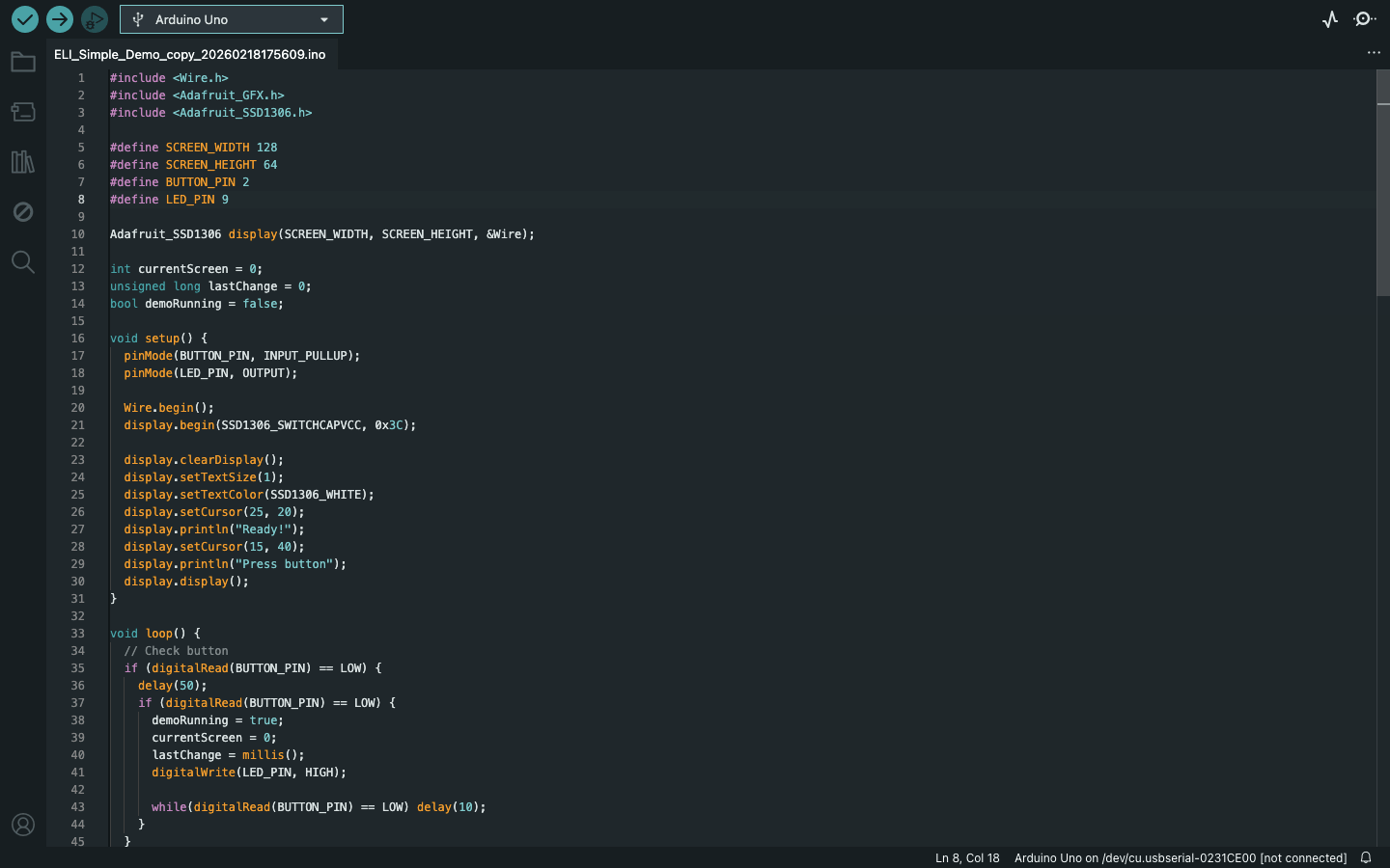
Week 4: Making a simple simulation for the menu structure
For this week's project development, since we learned about embedded systems, I wanted to work on my final project simultaneously as well. Instead of starting something completely new, I decided to make a simple demonstration of the menu structure I had designed earlier.
I began by creating a basic simulation in Wokwi, using the draft menu layout I made last week.
In Wokwi, I added the components needed for the simulation: an ESP32-C3 microcontroller, LEDs, resistors, a breadboard, and an OLED display. The simulation itself is very simple, it just cycles through the different menu screens to give a rough idea of how the interface might look. At this stage, the goal was mainly to visualize the flow rather than build a fully interactive system. I plan to improve this later by adding proper inputs and navigation logic.
This is the first simulation I made, which only had a few components:
This is the second video, which has more components, and I updated the code to cycle through different menu structure for the demonstration:
You can access my Wokwi simulation here.
After testing the simulation, I tried building the same circuit using real hardware. I first used a Seeed Studio XIAO ESP32-C3 (bare module), since there wasn't enough time to design and fabricate a custom board. I placed it on a breadboard and wired the connections similar to the simulation. However, the setup didn't work as expected. To keep the demonstration moving, I switched to an Arduino Metro board instead. The hardest part was to program the OLED display, instead of working like the simulation, it got stuck at 'Hello'. After a lot of time spent on trying to get the OLED to cycle through different screens, it turns out the code was too long for the OLED to work so I used Claude AI to shorten the code. And it finally worked.

Here is the video:
This week, since I had to browse through a datasheet for a microcontroller, I browsed through the datasheet for the microcontroller I'll be using for my final project as well, which is the Xiao ESP32 C3 microcontroller.

Week 5: Testing flex sensors for my user interface
This week, I built upon my existing circuit to test the menu navigation using a flex sensor instead of physical buttons since I will be using flex sensors as my main input method. The interface now responds to different levels of bend:
- A light press scrolls through the menu options.
- A longer, deeper press confirms a selection.
I also used both visual and audio feedback: the LED blinks and the buzzer beeps to confirm each scroll and selection. Although the timer functions aren't fully programmed yet, the menu structure responds reliably to the flex sensor, which was the main goal for now.
You can download my Arduino code here.
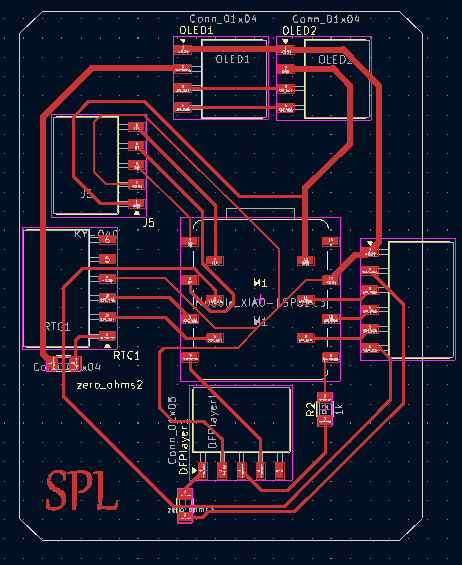
Week 6: Designing the PCB for my final project using KiCad
This week, after learning how to create schematics and design a PCB, I tried making a PCB for my final project. The board includes a Xiao ESP32-C3 module and connector pin headers for my components. It took a long time to get everything right since I'm still a beginner, but the PCB design turned out well. Although it will likely need many modifications as my final project idea becomes clearer, this design serves as the first draft and the foundation for all future PCB designs for my project.
This is the schematics:
.jpg)
And this was the PCB I designed for my final project:
.jpg)
I also generated an RML file for the PCB design, so it's ready to be milled next time.
.jpg)
I got to think about the components in detail for my final project too:
You can access the component list here.
Week 7: Final project components
This week, I was able to identify more suitable components for my final project and replace some of the earlier choices due to some issues, such as the camera being too large and the flex sensor not being a convenient input method. I also did some research on alternatives, and these are the components I have considered so far for my final project:
- Xiao Esp32 C3
- DS3231 RTC Module
- KY-040 Rotary Encoder Module
- 1.3 inch OLED display module
- arducam mini 2MP plus (B0067)
- DFPlayer Mini MP3 Module
- 8Ω 3W Mini Speaker


For the menu navigation, I decided to use a rotary encoder instead of flex sensors or buttons since it can do multiple functions and also works like a button when pressed.
Note to self: Test the menu structure using a rotary encoder.
Week 8: Modifying PCB
This week, I modified the PCB I made for week 6 with updates on the new components. I changed the flex sensor with the rotatory encoder.
This was the board I milled out:
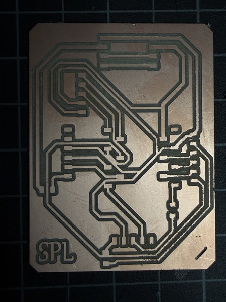
But later on, I found out there were multiple short circuits 😭 😭 😭. Next time, I have to make sure the routes are not too close to each other 🥲

Okay I have to work on my final project board again. And to understand my project better, I also created a pseudocode with the help of AI.
This was the prompt I used to generate the pseudocode and I also pasted a lot of stuffs about my final project from my page to give claude ai context.

1. Start up
BEGIN

  // Turn on and prepare all parts
  Setup XIAO ESP32-C3 microcontroller
  Setup OLED display
  Setup KY-040 Rotary Encoder
  Setup Arducam Mega SPI camera
  Setup DS3231 RTC (clock module)
  Setup DFPlayer Mini + 8Ω 3W Speaker

  // Show welcome message and play a sound
  Show on screen: "Hello! I'm E.L.I."
  Play sound: "startup sound"

END STARTUP
2. Main Loop
WHILE ELI is on DO

  // Check what the user is doing
  encoder_action ← read rotary encoder()   // did user rotate or press?
  current_time   ← read clock()
  camera_image   ← take photo()

  handleInput(encoder_action)       // handle menu navigation
  checkPosture(camera_image)        // check if user is sitting well
  updateTimer(current_time)         // count down active timer
  checkIdle(current_time)           // go to sleep if no activity
  updateScreen()                    // refresh the OLED display

  Wait 100ms

ENDWHILE
3. Rotary Encoder Input
FUNCTION handleInput(action):

  IF action == TURNED RIGHT THEN
    Move menu cursor down by 1

  IF action == TURNED LEFT THEN
    Move menu cursor up by 1

  IF action == BUTTON PRESSED THEN
    Select the current menu option
    Play sound: "confirm beep"

END FUNCTION
4. Posture Check
FUNCTION checkPosture(image):

  result = analyzeImage(image)

  IF result == SLOUCHING THEN
    Show on screen: "Sit tall!"
    Play sound: "posture alert"

  IF result == NO PERSON DETECTED THEN
    Pause the timer            // don't count focus time if away

END FUNCTION
5. Focus Timer
FUNCTION updateTimer(current_time):

  IF timer is running THEN

    remaining ← timer_end_time - current_time
    Show on screen: remaining time

    IF 90 minutes have passed THEN
      Show on screen: "Stand and stretch!"
      Play sound: "stretch reminder"
      Reset stretch reminder counter

    IF remaining time == 0 THEN
      Show on screen: "Session done! Take a break."
      Play sound: "timer complete"
      Stop timer
      Go back to Home Menu

END FUNCTION
6. Focus Blueprint
FUNCTION showBlueprint():

  // Display summary of past focus sessions
  // Data is stored in ESP32 internal memory (no SD card)

  Show on screen: total number of sessions completed
  Show on screen: best focus time of day
  // e.g. "Sessions: 12 | Best: 6 AM"

END FUNCTION
That's all for this week!
Week 9:Making the final project board again.
I found out that the board I milled out last time had a lot of short circuits, so I modified the pcb and the schematics so that the routes are not too close too each other and milled another one out again.This was the RML file:

Okay so far no probblems and this time the routes did not join together.

I also soldered all the connectors and other components onto the board as well.

Just when I thought I was done with my final project board, I found another issue while testing the connections with an ammeter 🤦♀️

The bottom left part of the pcb board was not connected to ground 😭. How could I have missed that 🤦♀️. It was my carelessness again and my impatience to get the final project board ready X_X .
Okay so I have to remake the board again, this time with all the connector connected to ground. I don't think there were any other issues for now, well I hope not.
Week 10: Testing the menu with the encoder:
I tested the menu structure this time using the rotary encoder instead of the flex sensors to identify possible issues with using that as the main input method. I used the arduino code of menu structure from last time except modified it with the rotary encoder and removed the flex sensors and buzzer.
Here is a video of the demonstration:
When I rotate the encoder clockwise, it scrolls down, and when I turn it anti-clockwise, it scrolls up. Pressing the encoder selects an option. Overall, navigating the menu felt decent using the rotary encoder,it was much better and more convenient compared to the flex sensors.
The menu structure is just a rough draft to show the available options, and some parts still need improvement. The “go back” option especially needs to be made better too.
And since this week was output week, for the assignment, I tested an oled to make those robot expressive eyes using the FluxGarage RoboEyes Library.It was just to learn how to get those eyes and to cycle moods although I have to plan out all the specific moods for my bot and also plan hoe they would cycle accordingly to the envrionment, but I'll figure that out later on soon.
That's all for this week!
Week 13: Figuring out the Exterior design
I realized I was too focused on the menu, that I didn't pay much attention to the exterior design so I remade a skecth of my final project and how each part would connect to each other.
Change of plans, I want my final project to be a penguin instead of a whale 🤷♀️
Week 14: Testing methods for posture detection.
Since this week was about applications and interfaces, I decided to test the posture detection aspect of my final project using the xiao esp32 c3 board from output week and connecting it to a buzzer so that everytime I slouched, the buzzer would beep once. I used MediaPipe and OpenCV because MediaPipe already has a pre trained pose model that runs well on the CPU and gives me the key upper body points like shoulders, eyes, nose, and ears, which I need for posture detection for this week since I don't have the time to do the ARduino C++ coding and I only needed to test the methods for this week. OpenCV is used to handle the webcam feed in real time, flip the image, and process the frames without needing extra tools.
Even though I won’t be using MediaPipe or OpenCV in my final desk bot, this week was useful for testing and researching the posture detection idea.
The main thing I learned is that accurate posture detection is harder than expected in a real working setup. Even when I was sitting still, the system kept switching between “good posture” and “slouching.” I had to keep adjusting the code by changing thresholds, and adding a delay after each change but small movements like breathing or shifting slightly still caused errors. This is an important issue for my desk bot because it’s meant to work while someone is studying or working, where natural movement is there. If it reacts to every small motion, like looking down at notes, it becomes annoying and not useful. So for the final Arduino version, I realized the system should focus on sustained posture over time and not single frame detection. Instead of reacting instantly, it should only change state if poor posture is maintained for around 15 to 30 seconds.
For the final project, I plan to use a lightweight on device approach in Arduino C++, where the XIAO ESP32 C3 processes everything locally using the Arducam. It won’t rely on a laptop or libraries,it will work as a standalone device because the XIAO has limited memory, about 400KB of RAM and can’t run heavy tools like MediaPipe, or OpenCV.
Methods
These are the methods I plan to use for now for the posture detection part of my final project:
- Shoulders get closer together:When you slouch, your shoulders roll forward and look narrower. The computer measures the distance between them. If they become much closer than when you sit straight, it thinks you're slouching.
- Head moves forward:Good posture keeps your ears roughly above your shoulders. When you slouch, your head pokes forward, making your ears sit higher than your shoulders. The computer notices that gap and counts it as a slouch.
- One shoulder drops lower:If you lean to one side, one shoulder ends up lower than the other. The computer checks the tilt of your shoulder line. Too much tilt means you're slouching sideways.
- Head droops down:Slouching often makes your head drop downward. The computer compares the height of your nose to your shoulders. If your nose is significantly lower, it's a slouch.
- Face looks bigger:When you lean forward, your face gets closer to the camera and appears larger. The computer compares your face width to your shoulder width. If that ratio increases, you're leaning forward – confirming a true slouch, not just sitting crooked.
Modifying PCB for my final project board:
This is the updated schematics and this time I made sure all the connectors were connected to ground.

This is the pcb and I've flipped the connectors for the oleds and the camera so that they will be facing outwards to make connecting easier.

Hopefully this time, there would be no short circuits and other errors 🤞

This is the schedule for my final project since the final presentations are drawing much nearer.

You can access the schedule in google sheets here.
That's all for this week!
Week 15: System Integration and Milling PCB board:
This week, I was able to mill out my final project PCB board and solder all the components:


I was able to design the deskbot in Fusion as well. I used fusion forms to shape the overall the penguin and then later on encoporated all the liitle details such as holders and framings for electronics back in Solid workplace.It took me all week to design the desk bot so I could only properly make the standoffs/holders for the externally mounted components. Next week, I'll try as much as possible to finish all the holders and I have to finish making the joints to join the shells and plates as well.

Mounting Internal components:
All the internal electronics are to be mounted on the back shell. Internal components such as PCB board, rtc etc.There are two back shells, into which the front plates will slide into, the body backshell and the backshell for the penguin head.Although,I still have to finish making the standoffs and holders for all the internal components.


Mounting External components
All externally visible components such as the oleds,rotary encoder and camera are to be mounted on the front plates.Thereare two front plates- the face plate and the belly plate. The modules will be secured using standoff/pillars tat will go through the module holes and a cap for the standoff will be used to lock the module in place.


That's all for this week.
Week 16: Testing the second draft for the menu
This week, I got to work on the menu system much more and test my final project as well.

And I realized I hated the name ELI so switched to MR. Flippers instead 😌.
I tested the oled, rotary encoder and the RTC module since some of the components weren't available currently in the lab.There was one DFPlayer which I am planning to test shortly after but I couldn't find the 8ohms 5 W speakers.Maybe I can use another one instead just for testing.
After making all the connections, I downlaoded all the required libraries in Arduino IDE and I prompted Claude AI to modify my initial version of the menu I tested last time except this time to make it work like the real thing with all the timers and everything. I'll never forget everything you've done for me Claude 🥹


IT WORKED!!! 😆 I was a bit doubtful of my board because of the amount of times I had to resolder because of cold solder joints and I had a lot errors while uploading the code which was most likely caused by the USB cabel and it took me half a day to fix that connection problem and debug the code to get it to work the way I wanted.
I even gave MR. Flippers a personality to make it more fun 😁. I wanted productivity feel like a mission and as if you were playing a simulator.I still have to improve it ofcourse, this is just the second draft but I'm glad that I got to finalize the basic options for the menu.
I tested the pomodoro timer and this was after the 25 min:


I was able to make the standoffs for all the components and modify my design more. I imported my pcb from kicad to help design the standoffs.

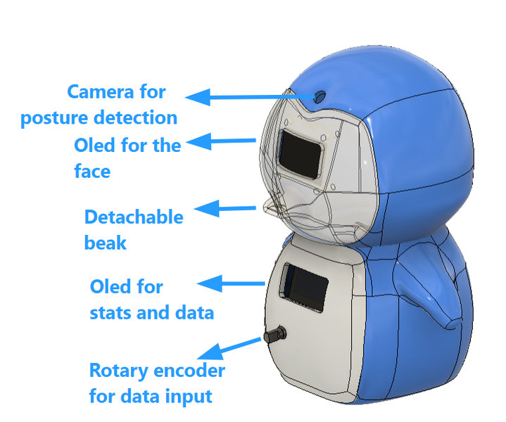
These are all the externally mounted components for the body:

This is whta the inside looks like:
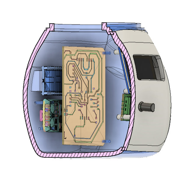
The internally mounted components which are the RTC and the dfplayer are mounted right behind the pcb. The rtc is mounted using standoffs while the dfpayer is mounted using a custom made holder that is joined to the body shell.

The oled for the face is mounted using standoffs too:

The complete overview so far:
I am not done designing the holder for the camera,speaker and I have to modify the design to make the different pieces connect as well.
Progress update, I 've printed the first prototype of MR Flippers and found out new problems such as the standoffs being extremly fragile, the twist and lock system not working etc so I've modified the deisgn and gone through several reprints.


While the components were printing, I was able to work on my electronics part. I replaced the arducam mini with the xiao esp32 s3 sense camera and the 2 microcontrollers will be communicating via UART.
